
Steel grating made
to your design conditions
Bearing bar profile, pitch and end finish are chosen to suit the site, and every panel is fabricated to the dimensions on your drawings.
How steel grating is built
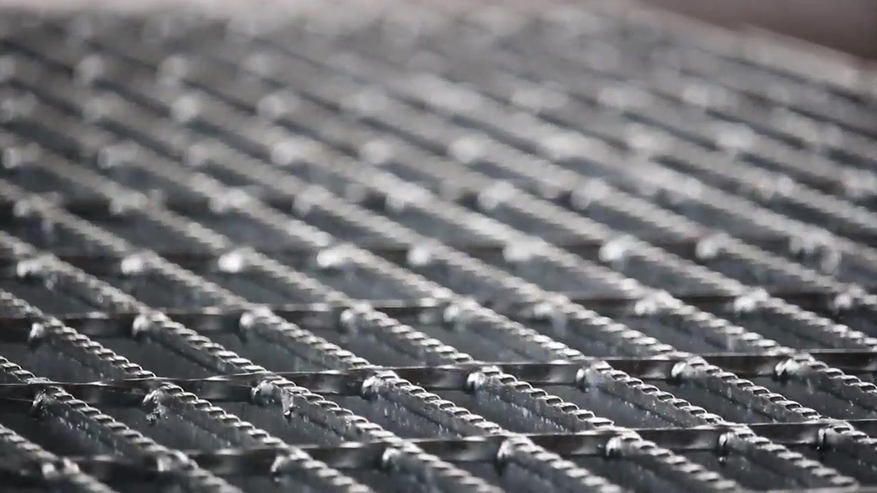
Steel grating is an open-grid floor panel. Load-carrying bearing bars stand on edge at a fixed spacing (pitch), and cross bars run across them, joined into a single piece by electric resistance projection welding.
It lets light, air and rainwater through and has a high strength-to-weight ratio, which makes it the standard choice for plant walkways, platforms, trench covers and stairs. The panel ends are either closed with end bars (banded type) or left open (open type).
Bearing bar profiles
Grating is classified into four types by bearing bar profile. Each is available as banded type or open type.
I-Bar Grating
Grating whose bearing bars have an I-shaped cross section.
Flat Bar Grating
Grating whose bearing bars are plain rectangular flat bars.
Serrated I-Bar Grating
Grating whose bearing bars combine an I-shaped section with a serrated top edge.
Serrated Grating
Grating whose flat bearing bars have a serrated top edge.
Standard dimensions
| Bearing bar profile | I-bar, flat bar, serrated I-bar (SI), serrated flat bar (SF) |
|---|---|
| Bearing bar pitch | 12.5 / 15 / 25 / 30 / 35.3 / 40 mm |
| Cross bar spacing | 100 mm |
| Cross bar | Pitch 30 mm: 6×6 square bar · 35.3 mm: 8×8 square bar · 15 mm: ø6 round bar · 12.5 mm: ø5 round bar |
| Max. standard width | 995 mm (set by number of bearing bars and pitch) |
| Length | Made to design dimensions (length = bearing bar direction, width = cross bar direction) |
| End finish | Banded type (end bars) / open type (cut end) |
| Material | Hot-rolled carbon steel bar, JIS G3101 SS400, SS275 |
| Surface finish | Hot-dip galvanizing to KS D 8308, JIS H8641, ASTM A123 |
| Fabrication tolerance | Per NAAMM (National Association of Architectural Metal Manufacturers) |
Bearing bar sizes
I = moment of inertia, Z = section modulus (per bearing bar)
I-Bar
| Type | Size H×W×T (mm) | I (cm⁴) | Z (cm³) |
|---|---|---|---|
| I-25 | 25×5×3 | 0.605 | 0.484 |
| I-32 | 32×5×3 | 1.251 | 0.782 |
| I-38 | 38×5×3 | 2.083 | 1.096 |
| I-44 | 44×5×3 | 3.221 | 1.464 |
| I-50 | 50×5×3 | 4.609 | 1.844 |
| I-50 (7T) | 50×7×4 | 6.432 | 2.573 |
| I-55 | 55×7×4 | 8.488 | 3.086 |
| I-65 | 65×7×4 | 13.960 | 4.295 |
| I-75 | 75×7×4 | 21.387 | 5.703 |
Flat Bar
| Type | Size H×T (mm) | I (cm⁴) | Z (cm³) |
|---|---|---|---|
| F-25 | 25×5 | 0.651 | 0.521 |
| F-32 | 32×5 | 1.365 | 0.853 |
| F-38 | 38×5 | 2.286 | 1.203 |
| F-44 | 44×5 | 3.549 | 1.613 |
| F-50 | 50×5 | 5.208 | 2.083 |
| F-50 (6T) | 50×6 | 6.250 | 2.500 |
| F-65 | 65×6 | 13.731 | 4.225 |
| F-75 | 75×6 | 21.094 | 5.625 |
| F-90 | 90×6 | 36.450 | 8.100 |
Serrated
| Type | Sizes | Pitch (mm) | Cross bar |
|---|---|---|---|
| Serrated I-bar | SI-25 to SI-44 (×5×3) | 30 / 15 | 6×6 / ø6 |
| Serrated flat bar | SF-25 to SF-44 (×5) | 30 | 6×6 |
Serrated bars have the same unit weight as unserrated bars of the same size.
Unit weight
kg/m², after hot-dip galvanizing
| Bearing bar | Pitch 30 mm | Pitch 35.3 mm | Pitch 40 mm | |||
|---|---|---|---|---|---|---|
| Banded | Open | Banded | Open | Banded | Open | |
| I-bar 25×5×3 | 31.4 | 29.5 | 27.4 | 25.4 | 25.1 | 23.1 |
| I-bar 32×5×3 | 38.6 | 36.1 | 33.8 | 31.3 | 30.9 | 28.4 |
| I-bar 38×5×3 | 44.2 | 41.3 | 38.6 | 35.6 | 35.2 | 32.2 |
| I-bar 44×5×3 | 50.5 | 47.1 | 44.0 | 40.5 | 40.1 | 36.6 |
| I-bar 50×5×3 | 55.4 | 51.5 | 48.3 | 44.4 | 44.0 | 40.1 |
| I-bar 50×7×4 | – | – | 67.5 | 62.8 | 61.5 | 56.8 |
| I-bar 55×7×4 | – | – | 73.2 | 68.0 | 66.6 | 61.4 |
| I-bar 65×7×4 | – | – | 85.2 | 79.1 | 77.4 | 71.3 |
| I-bar 75×7×4 | – | – | 97.4 | 90.3 | 88.5 | 81.4 |
| Flat bar 25×3 | 23.3 | 22.1 | – | – | – | – |
| Flat bar 32×3 | 29.1 | 27.6 | – | – | – | – |
| Flat bar 38×3 | 34.2 | 32.4 | – | – | – | – |
| Flat bar 25×5 | 38.1 | 36.2 | 33.2 | 31.2 | 30.3 | 28.3 |
| Flat bar 32×5 | 48.1 | 45.6 | 41.8 | 39.3 | 38.1 | 35.6 |
| Flat bar 38×5 | 56.5 | 53.5 | 49.1 | 46.1 | 44.7 | 41.7 |
| Flat bar 44×5 | 65.0 | 61.6 | 56.4 | 53.0 | 51.3 | 47.8 |
| Flat bar 50×5 | 73.6 | 69.7 | – | – | – | – |
'–' means no standard unit weight data for that combination. Sizes not listed can also be made to order.
Stair treads
End plates are attached to both ends of the grating, which is then welded or bolted to the stair stringers.
| Connection | Welded type / bolted type |
|---|---|
| Width (bolt hole spacing) | 215 mm (120) · 245 mm (150) · 275 mm (180) |
| Length | 500 – 1,200 mm |
| Bearing bar | F25×5, F32×5, I25×5×3, I32×5×3 |
| End plate | Fillet welded to every bearing bar, 3 mm minimum |
Fixing methods
Chosen by vibration, need for removal and installation speed.
Saddle Clip
Bolted in place and removable.
Upper / Lower Clip
Clamps from above and below; resists vibration.
Self-drilling Screw
Fast installation with no pre-drilling.
Field Welding
For areas that never need to be removed.
Hot-dip galvanizing
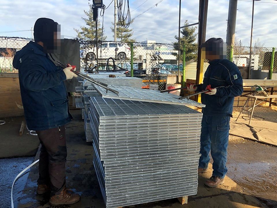
After fabrication, the grating is dipped in molten zinc so that every surface is covered with a zinc coating. This protects it from corrosion outdoors and in humid plant environments.
Galvanizing is done to KS D 8308, JIS H8641 and ASTM A123, and coating thickness and surface condition are measured before shipment.
Load review
Allowable load and deflection depend on span, load type (pedestrian, vehicle, concentrated load) and support conditions. Send us your layout drawings and load conditions, and our R&D center will review them and propose suitable bearing bar sizes.
Specifications may change without notice for product improvement.